Change your crank oil seals and bearings
Quite involved as it involves stripping the complete the top end, this pretty near a full engine rebuild.
Tools you will require are :- Flywheel puller, flywheel holder, T bar extractors (or 2x long M6 bolts), circlip pliers, a source of heat such as a heat gun, spanners, socket set, screw drivers.
![]()
![]()
![]()
![]()
Scope
This can be quite involved this one, so you have been warned! Special tools required are the flywheel holder, and the flywheel puller. You will also need an impact driver and to have a source of heat, probably a blow torch is best, other methods will be described later on. The usual hammers, screwdrivers, sockets, etc are also on the tools list.
First we need to take the floorboards, off on both sides, 8mm nuts secure these, on the outer runner strip, and in the central bridge piece. On the kick-start side, also remove the leg that supports the rear of the floorboard, these should be 11mm. Exhaust, held by two 13mm nuts, and one 10mm nut down by the tailpipe is next, there may also be, depending on your machine, another 11mm nut tucked away underneath to the rear of the box section of the exhaust. Last there should be a clamp, where the silencer meets the U bend. You may also have to tap, using a length of wood, the box away from the U bend, as it tends to rust and coke itself on.
Undo the engine oil plug, and drain oil. Carb, undo the 8mm clamp bolt, and again from the rear with a piece of wood, tap the carb off. No need to undo all the cables, just be careful to tuck the carb away so it will not get damaged. Undo and remove all the remaining 10mm nuts holding the chain case side on, remove the chain case, again it may need a whack with a rubber hammer, unhook the clutch cable from the arm.
Moving round to the other side now, remove all the 8mm bolts round the flywheel housing cowl, and the two on the side for the cylinder head cowl. Loosen the 13mm bolt at the top of the cowl, but not tight on the U bend. This now allows you access to the two 11mm nuts that hold the down pipe on. The one on the flywheel side is a touch awkward! With the U bend off, look between the rear wheel and the flywheel, there is a rubber bump stop on top of the casing, remove this by prizing a screwdriver in the bottom off it. Now you can take the rear shock absorber off to let the engine drop down. The cylinder cowl you have just undone will now slide off when you take the spark plug out. Undo the four cylinder head bolts, in a diagonal method, slide the head off, the head gasket, and the barrel. You may find the inlet manifold will catch on the bodywork, but a small amount of twisting and force will allow you to take it off. If you do not want to do this, just unbolt the manifold and take it off.
With the piston still in position, trap a piece off wood between this and the crank case mouth. Be careful that the piston will not slip off and break. With the piston moving down against the wood, time to take the front sprocket off. Loosen the two 10mm bolts that hold the chain tensioner on, scalene the chain. A 14mm bolt is used to hold the front sprocket arrangement on, go careful when first undoing this that the piston is in position on the wood and is not going to move. Slide all the items of the front sprocket set up off and out the way, including a small oil thrower cup washer at the bottom of this set up!
Back round to the piston, remove the two circlips that retain the gudgeon pin, I use a socket extension bar of the same size to tap this out! Piston, small end etc, take them off and put them to one side. Round to the other side, time to take the flywheel and parts off. first the flywheel holder, put this in position and undo the nut in the centre (17mm) which is left hand thread, it will undo turning clockwise. With the nut removed, insert the flywheel re-mover and extract the flywheel.
Before you start to remove the stator plate, make a mark that will allow you to re align the stator when re-fitting, mark both the stator and housing by scribing a mark with a screw driver or sharp object. Unplug the wires from the stator plate in the junction or rectifier box, un thread them so they are free. Three nuts hold the stator on, and a further three bolts to undo will allow you to start taking the stator housing off. You can use the special tools to remove the housing, but you can easily use two 10mm bolts of around 6mm plus in length to remove it. You will find two extra holes that had nothing in them, one at twelve-o clock and one at six. Using equal turns, otherwise you can easily strip the threads, tighten the bolts into the housing again take it easy the threads are delicate. If the threads have gone in here, the only way to remove the housing is by a long metal rod and hammer and banging the housing off from the rear, again equal amounts around the housing and hit it as near to the centre as you can. Hopefully the bolt method will work and the housing now starts to come off. It will be fairly tight as you are breaking the two seals that run on the crank.
It is now easier than it was when the housing was in position, to remove the two screws that secure the two wiring plates in position. There is a rubber seal in between these two plates also, slide them all off along the wiring, you can now remove the stator from the housing.
Once the housing is off, turn the crank to BDC (the conrod at its lowest point) tap the crank from the front sprocket side, out of the housing, you will need to turn the crank at an angle to remove it completely. Four screws hold a plate on where the crank has just been taken out, up against the drive side bearing. The impact driver is needed to remove these, as they are dot punched at the factory. If you do not have access to an impact driver, you may just about get away with a correct fitting screwdriver, while twisting the screw undo, tap the end of the screwdriver with a hammer. Best to get an impact driver though!
Remove the oil thrower gasket up against the bearing, push the seal out of the plate you have just taken off, notice it will only come out one way because of a lip on the plate. If you are not renewing the drive side bearing leave it in place. If you are, you will need to find a socket that fits through the hole left when you took the front sprocket, heat this housing up using a blow torch and knock the bearing out, using the socket and hammer. re-fitting the new bearing is in reverse of this, just make sure you use something that is large enough to place the pressure of hitting on the outside track. Smearing the bearing with grease on the outer track will help, just make sure the bearing goes in square, other wise you will damage the track.
Last thing to take apart is the mag or stator plate housing, two seals, some spacers and a bearing all need to come out. This can be a little tricky so if you are not sure at all, you might want to pop it along to a dealer to get the seals renewed! Some people just renew the one oil seal, is can be false economy but then again it is hard to re new both oil seals, damage to the mag side bearing is possible and easy to do. You have been warned! Just for the brave, the method of removal is this: -
Read ALL of the next section first, and then do the job!
Remove the large circlip that sits on top of the oil seal. Flick the oil seal out with a screwdriver. (If you are just replacing this one seal, refit new seal and old circlip in the reverse way to removal). There will be on Li, SX, and TV machines a small spacer ring (used with bearing NU205), take this out also. Now secure the housing in a suitable way, what we need to do is heat the housing up, but still allow us access to be able to tap the bearing out.
Remember it will be harder to heat the housing and then place it somewhere safe, as it will be hot to hold! The best heat source to use it is a blowtorch (butane burner, or calor gas burner), heat the housing up, and just make sure you don't melt it. Gas ring on your oven (when the wife is not looking) camping gas stove, can also be used, but just remember there will be deposits of unburned oil on the inside of the housing that can burn off, causing small holes in your carpet. Use a tray or similar to put the housing on!
Now what we are doing by heating the housing up is expanding it, so the bearing will not be so tight to remove. For removal, you will need to find a socket that fits the hole (the one that faces out when fitted, the smallest one) as tight as possible but still fits through. This is because if you use a smaller one it will not fit on the outer track of the bearing, so when you start hammering it out, you will defiantly need a new bearing. With enough (but not too much) heat in the housing you should be able to gently tap the bearing out, the remaining oil seal and cup washer will all fall out also, so take care as they too will be hot!
If you are re-placing you're mag side bearing a word of note. You will need to either have the special removal tool or take it to your local Lambretta Dealer who will be able to remove for a small fee. On no account should you try and remove it with heat and tapping it etc damage will occur to the crank!
That's it, time for checking everything in site and lots of cleaning! Clean all old gaskets from all surfaces, I also scrape all old oil deposits form all surfaces.
One note on the crank, it is acceptable for side play, but you should not have any up and down movement in the conrod.
Piston, if it has scores or burn marks, a fine grade of wet and dry sanding paper can be used to get the worst off. Clean the piston rings and make sure the grooves they sit in are clean.
It is a good idea to flat the cylinder head while off as well, to do this you will need a completely flat surface i.e. a piece of glass or a mirror, sticky backed sanding disc stuck onto the mirror or glass. Place the head on the sanding disc and use rotary movement, sand the head. Turn the head 90 degrees, and repeat, keep going until you have completed the full circle.
With everything clean, your new oil seals and gaskets, bearings if needed, you are ready to re-assemble.
Place the mag or stator housing so that the inner part faces upwards. Now you need to re heat the housing, not as much as when removing but still needs heat! Keep the heat at the top of the housing. When heated, fit new seal carefully as the housing is hot! with spring facing towards you (it will end up facing into the crank when you have finished) Fit the L shaped cup washer, if your old on is not damaged it will be fine to use this, otherwise fit new. Using again a socket or similar, again making sure that what you use, puts the pressure on the outer track, knock the bearing in position. Make sure it goes in square, tap it fully home. Again Li SX and TV models, if you are using the original size of bearing (NU205) fit the spacer washer. GP models and machines using the larger bearing (NU2205) do not use this spacer.
An alternative method is to stick the bearing in the freezer along with the pea's for ten to fifteen minutes, this shrinks the bearing to fit the mag housing.
Fit the larger seal in the housing again making sure the springs of the seal end up facing the crank when re-fitting. Re fit the circlip, put this assembly to one side.

Here we are starting with the drive side bearing set up, shown are the parts needed to fit the bearing. Good quality grease, bearing, gasket, oil seal and plate, plus four retaining bolts.

There are three methods to fit the drive side bearing, heat the casing by means of blow torch or similar, freeze the bearing as it makes it shrink, or buy a bearing press tool. There are manufacturers of tools specifically for Lambretta, if your going to make a habit of doing these jobs they are well worth the expense. Using one of these methods, press the bearing into the engine casing, it does not matter which way round it goes, but it is important that it is pressed all the way home. You can check this by looking at it through the chain side of the casing, it should fit right up tight against its housing.

Once the bearing is pressed home, smear the balls of the bearings with high melting point grease,

The round gasket is then fitted, some gaskets will not fit this housing perfectly, do not worry, just simply and carefully push the gasket edges into the housing with a flat screwdriver, just be careful when doing this.

Next we need to fit the oil seal to the plate, the picture here shows the correct way round it goes. The spring around the oil seal should face the the crank when it is finally assembled. Four new screws are used, it's always best to use new ones here as the old ones almost certainly will be damaged when removing them. New ones from most dealers will now be supplied as high tensile Allen key headed bolts, it is much easier to secure and do this type of screw. Lock-tite is always sensible on these bolts,
The plate is diagonally torque'd, this makes sure the plate sits down evenly, keep going around them until you are sure all four bolts are secured as tight as they can be, there is no torque setting for these bolts, but you should tighten them fully until they will turn no further.

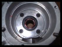
With this picture you can see that the oil plate is fitted correctly, it is vital that the plate is secured fully home and is flush as in the picture. If the plate sits proud and is not secured correctly, your crank will rub against it and not turn correctly, damage will occur.

Place the mag or stator housing so that the inner part faces upwards. Now as with the drive side bearing you need to either heat the housing, keep the heat at the top of the housing. When heated, fit new seal carefully as the housing is hot! with spring facing towards you (it will end up facing into the crank when you have finished) Fit the L shaped cup washer next.

Now we need to fit the bearing, it comes in two halves, put the inner to one side as this must be fitted to the crankshaft. Either with your bearing tool or by using a socket or similar, make sure that what you use puts the pressure on the outer track, knock the bearing in position. Make sure it goes in square, tap it fully home. Li SX and TV models, if you are using the original size of bearing (NU205) fit the spacer washer. GP models and machines using a GP crank with the larger bearing (NU2205) do not have or use this spacer.

With the bearing in position, fit the last larger oil seal, again with the spring side facing you, towards the crank when assembled. A large circlips holds everything in place. With every thing finished your mag housing should look like this!

Preparing the new crank, if you are not re-fitting your old crank you will need to fit the new mag side bearing inner track. The easiest way to do this is using a proper bearing drift tool, or a deep socket. To ease the fitting of the inner track, you can always place your cranksafht in the freezer for a few hours, this helps to shrink it a touch. Support the crank, if using a vice, use the jaws on the taper side of the cranks web cheek only, this helps to avoid twisting or knocking your crank out of true. Tap home around the whole inner track to make sure it is seated properly.

Fitting the crank is done by passing the shorter shaft through first, it is easier to get the crank at BDC, so the crank is at it's shortest. First smear a little grease on the drive side inner seal that we fitted earlier, a very slight coating is all that is needed. This helps the crank pass through it, less chance to nip the edge of the seal.
The crank should be pushed as far as possible by hand, rotating the crank slightly as you go, again to make sure you do not snag the edges of the oil seal.

Here we are using a special tool to pull the crank through, from the chain side position the space central on the bearing.

The front sprocket bolt is used to pull the crank through into position. If you do not have this special tool, fit the flywheel nut on the end of the crank, this stops you from damaging the thread on the crank, and using a rubber or nylon hammer, tap home the crank, again twisting as you go.

Here we can see again, the use of the tool to pull the crank through, we are also using a con rod holding tool to position the crank

Note how the crank is fully home now, flush to the drive side plate, but still turning freely.

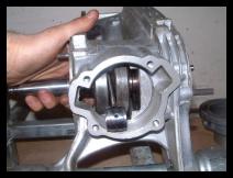
Before you fit the mag housing that we have built, the first step is the gasket for the mag flange, this will only fit one way, make sure all the holes line up with the gasket

Fit the mag housing assembly, this should be a pretty good fit, wiggle it into position, if its a little tight, a rubber hammer hit evenly around the edges will tap it home. If you are using your original one, it will need cleaning to make it fit easier. Once the mag housing is just about home, three nuts on the studs secure this. Again in a diagonal pattern tighten this fully home. Finally check the crank still turns freely.

Now you have the mag fitted, we can turn our attentions to stator plate.
Re position the stator roughly in the mag housing, fit new screws, gasket to the securing plates, that hold the wiring, again this just helps because there is not much space to do this when the mag housing is in position. Fit new mag housing gasket, it will only align one way with all the holes. There is a tab sticking out on the gasket, this lines up with a notch at the nine-o clock position on the crank case side. Make sure you align the three studs fitted, with the corresponding holes, push on, it will not go far. Use a rubber hammer to knock the mag housing home, refit three securing bolts, remember the top one has an arm to trap the wiring down. Align the stator plate up with the marks you made earlier, fit the three nuts to secure.
Round to the front sprocket side, fit the cupped oil thrower washer, cup but sits inwards, front sprocket assembly is located on to splines, line them up and push home, with the chain located on the teeth. Now take the outer washer (the bolt sits in it) push it down the spline. If you look on the front sprocket shaft you will see a small oil way hole. Using a felt marker pen, make a mark on this outer washer that lines up with the hole, this just eases re-fitting. Take it back off and refit other half to front sprocket, the two half moon parts locate together at their lowest point. Spring on next, then the outer cup you just marked with the bolt through it. Start to tighten the bolt, while looking at the mark you made and the hole, it is easier to locate properly. To finally tighten the bolt you will need to lock the chain to stop it rotating, I simply wedge the largest screwdriver I have in between the teeth of the cog and the chain. Tighten the front sprocket as tight as you can, the outer ring should at least partially cover the oil way hole on the shaft. A final check is to smack the assembly with a hammer, if it sounds hollow re tighten it, as it should sound solid!
Fit new chain case side gasket and the chain case side, re-fill with fresh oil making sure drain plug is back! Check that you have refitted the clutch cable into its arm, if not, use a pair of grips to move the arm forward and slip the cable in.
Refit the piston and barrel assembly using new gaskets, to base, head, inlet and exhaust. Some people find it easier to fit the piston and rings into the barrel first, then when the barrel is slid down on the studs, line the conrod up with the piston, (having first inserted the small end bearing in the conrod, slightly oiled) piston that just pokes out the bottom enough to be able to tap the gudgeon pin in and re fit the circlips. When tightening the head down, this should also be done in a diagonal method, to 20 N.M., (the book states 15 but 20 is better). Re-fit flywheel and then check that timing is all correct and present still.
Finally re-fit both cowlings, cylinder head and flywheel, re-fit, carb, exhaust, plug the wires from the flywheel back in to the junction box or rectifier.
Turn on and start up.