Wiring up extra lights
It is with great thanks to Steve Hanson for this article. Steve has taken considerable time to write this, and supply all pictures and diagrams.
Although we have a three spanner rating, if you follow this guide, you will find wiring up lights and accessories fairly simple!
![]()
![]()
![]()
Scope
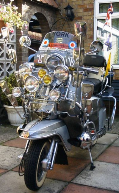
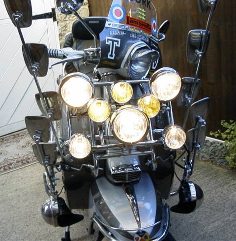
I run 3 large spots, 3 fog mini lights & 2 clear side lights. I also have a pair of old car chrome horns, a pair of car number plate neons to hold my switch housing and a pair of 6" bike underbody neons (Zeld Auto's - www.zeldautos.com) which light up at the same time as the switch neons so I don't forget I've left them on. So, in total I run 14 items with no bother.
What you Need
6v or 12v Battery (Auxiliary)
Battery charging regulator ( You could always keep charging manually with no reg )
30Amp Red cable
15Amp Black cable
Inline fuse holder with 10Amp fuse
Isolating switch
Wiring connectors, terminals etc
Good junction box ( Mine is in legshield tool box )
Switches ( One for each group of no more than 4 lights )
Switch Panel ( Optional, I used a Mini one )
Halogen bulbs ( Optional )
My Setup:
I have a 12v Electronic system with a battery charging outlet on the regulator. If you can't run to this expense then just buy a battery (£20) and keep charging it up every time you want to show off your lights. The reason for the battery is so that the lighting system is never going to overload your bikes loom etc as it is run independently from all else.
CLICK HERE TO SEE THE WIRING SETUP ON STEVE'S MACHINE
Instructions:
First, find a suitable out of the way place to mount your junction box. I used self adhesive Velcro to fix in place. As I said above, mine is in the legshield toolbox so it is out of the way of damp. The main reason it is in there is so that I can switch the isolator switch off and lock the toolbox door, then nobody can prat about with your lights when you leave the bike unattended.
Preferably inside your junction box you should have 2 separate banks of terminals, obviously 1 for Live and 1 for Earth.
Connect a 30Amp Red form your battery live terminal to one of the banks of connectors in the junction box. To make the other terminals live in this bank, loop 30Amp from main inlet source to other terminals. You should now have enough live feeds to light up your house. Now connect one 30Amp live wire from there to your isolator switch with the inline fuse holder in between. Remembering also that, the position of the switch needs to be easily accessible.
Now find a good Earth point on the bike, I have connected to the horn bracket. Bring in to your junction box one 15Amp Black cable and fix it to the second bank of terminals, also looping the others as before.
You now have a main source of Live & Earth for anything you want to run on your bike. I might go for a radio next, or even a telly!
Wiring up your Lights etc:
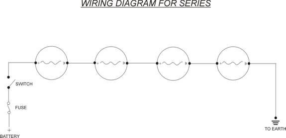
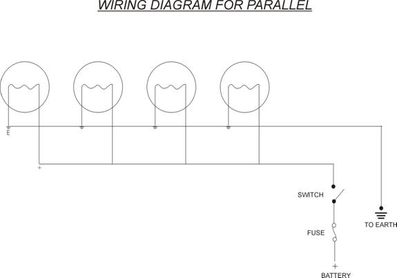
You can wire them in 'Series' or 'Parallel'
WIRING DIAGRAM FOR SERIES LIGHTING
WIRING DIAGRAM FOR PARALLEL LIGHTING
Parallel draws more from your battery but will make performance better. 6Volters I think are better to use series, experiment and see which suits yours best.
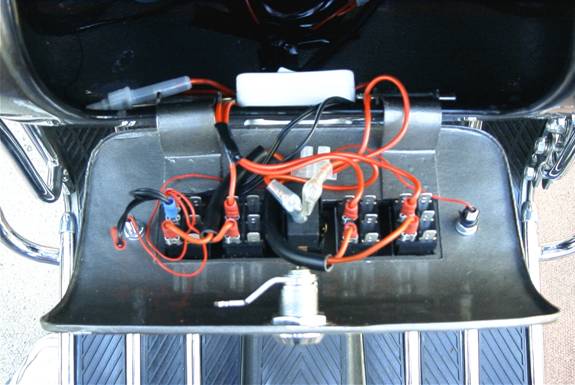
VIEW OF LIGHTING CONNECTIONS INSIDE STEVE'S TOOLBOX
I don't advise connecting more than 4 lights in a bank but there again I have not tried it. After all, what damage can you cause, blown fuse, burnt cable or at the very extreme a knackered battery. All replaceable and no effect to your bikes main electrics.
These are two more diagrams if you really want to go to town and be totally sure nothing will go wrong, but, as you are using an auxiliary battery, I don't think you need to go to these extremes.
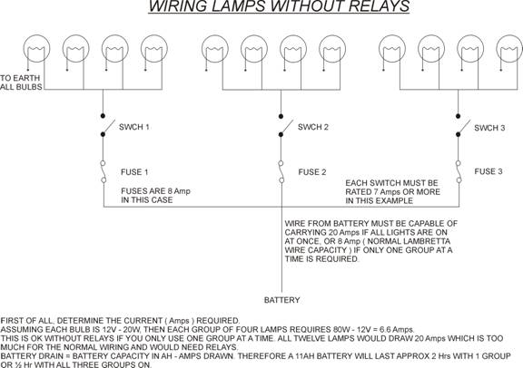
WIRING LAMPS WITHOUT RELAYS (2)
WIRING LAMPS WITHOUT RELAYS (3)
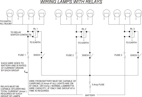
VIEW OF ISOLATOR AND FLUSH MOUNTED ROCKER
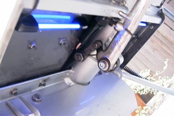
From the isolator switch, I bought a flush mounting rocker from a Diy shop for pennies, take another 30Amp Red and fix to this a connecting block. Decide how many switches you will need and fix them in place. Take a live to each switch from the block. A smaller Amp Red can be used in this instance. Don't forget that if you have already wired to your junction box then these cables will be live if you don't turn your isolator switch off.
The switches are now ready to connect your lights to.

Most lights are self earthing. If however yours are not, then simply connect the earths from each bank of lights direct to the earth terminals inside your junction box. I made this easier by taking the three leads from one bank to another connecting block, from the block I took one 15Amp black to the junction box. This way you don't have loads of wires all over the place.
Repeat as above for the live feeds for each bank of lights but this time take the live direct to the required switch. This is parallel wiring.
For series wiring, connect from your switch a live to the nearest light + terminal, from the - terminal of that light, connect this to the + of next light and so on to the last light where the neg then is connected in to the earth in the junction box.
Now is testing time! Turn on your isolator switch, turn the switch on and pray you have followed these instructions correctly. If you have light then just repeat the process for all the banks of lights or anything else you require.
I have found on my system that I can switch all on at once with no ill effect other than the battery wouldn't last too long without it being charged up while running.
These instructions are given free of charge and I accept no responsibility for electrocution, hair loss or otherwise.
Enjoy! Steve Hanson.