LCGB Forums

The ability to post messages is restricted to LCGB members. Any questions contact us at lcgbadmin@googlemail.com

Ignition testing kit.

Need help with a tuning kit, how do you tune your scooter, which kit should I choose, and all general tuning and modifcations questions are for in here.

Ignition testing kit.

Postby Captain Pugwash » Wed Nov 14, 2018 11:42 pm

Image
I normally use my mains powered oscilloscope when I want to check out an ignition but the size and 240 volts needed to run it make it a workshop/garage only tool.
I have seen many portable hand held scopes before, but they’re were in the past fairly expensive, but now the prices are a little lower.
Luckily a recent search found a scope available in kit form that I thought I would try.

The kit comes PRE SOLDERED or as a completely disassembled kit. It’s only a basic single channel scope but is very capable of ignition testing a lambretta. YOU NEED TO ORDER THE PRE SOLDERED KIT NOT THE DISSASSEMBLED KIT.
https://rover.ebay.com/rover/0/0/0?mpre ... 3495886809
If you do buy one of these cheap scopes, make sure you use the drop down option and choose a pre soldered kit, then when it arrives from CHINA it’s just a few screws and a little bit of reading to set it up. Then your ready to test your first ignition.
These are Available from eBay for less than £20 and are capable of testing the ignition waveforms produced from any Ducati type pickup and capable of a few other electrical checks on your scooter.
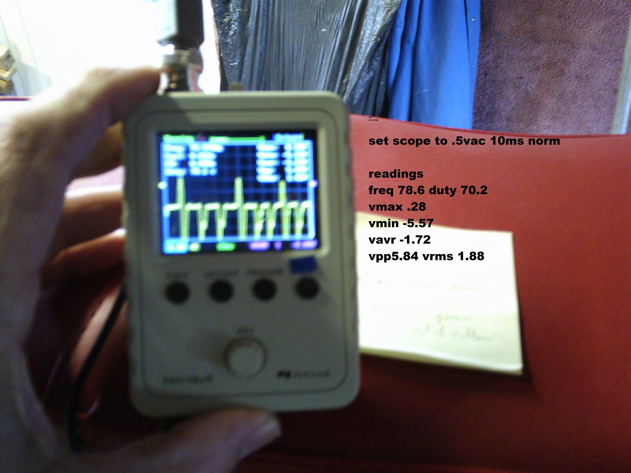
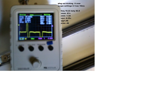
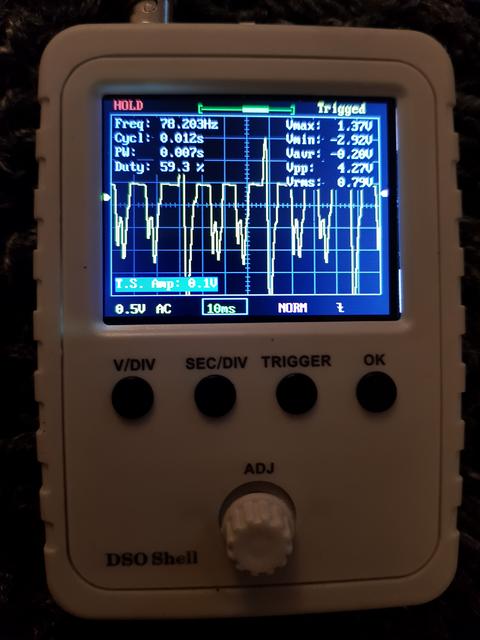
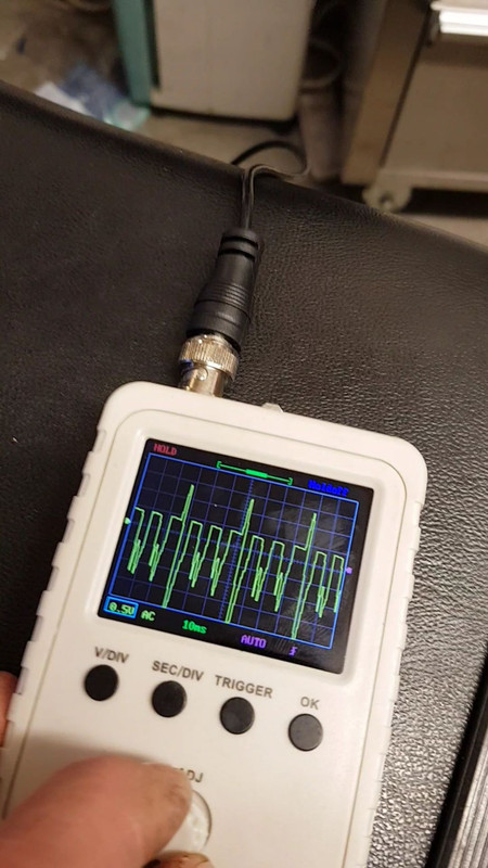
Here’s a link to a pic of the cheap scope I’m using. This is showing my pickup signal at tickover speeds.
Image

You will need a 9v power supply, again ebay will supply a battery box and lead. https://rover.ebay.com/rover/0/0/0?mpre ... 2904735360
And fit a 9v PP3 battery to it.

I’ve told a few others about these little test kits and thought I would share on here as there does seem to be some interest in this cheap little test kit.

When you use the scope The wave form will remain on the screen till you turn the scope off or over written whe you use it next, or the waveform can be stored and recalled later when the scope is turned back on. Measurement voltages and time scales of the waveform can also be displayed on screen. There are basic instructions with the kit but you will soon suss it out it’s not hard to use.

Finally managed to upload a short video of the scope in use


There’s a few sellers of this kit and some come with different leads but the two crock clips that make up the test lead that come with this version of the kit, make it ideal for clipping to the red and white wires from the pickup.
Last edited by Captain Pugwash on Thu Dec 06, 2018 11:29 pm, edited 4 times in total.
User avatar
Captain Pugwash
 
Posts: 422
Joined: Fri May 30, 2014 7:48 pm
Location: Liverpool

Re: Ignition testing kit.

Postby Fast n Furious » Thu Nov 15, 2018 2:18 am

Excellent post Captain.
That £20 scope almost does what my 20 year old, £500, Fluke storage instrument does.
Good find. ;)
Last edited by Fast n Furious on Wed Nov 28, 2018 6:46 pm, edited 1 time in total.
User avatar
Fast n Furious
 
Posts: 1507
Joined: Sat Nov 19, 2016 3:56 am
Location: York

Re: Ignition testing kit.

Postby grandpa » Thu Nov 15, 2018 4:21 pm

+1
Excellent post captain
I had looked at these some while ago but now having seen someone using it will look again.My 10 year old grandson is interested in eIectronics I have just helped him make a Van De Graaf generator that he saw on youtube.Many years ago I used to carry a scope to set up the seek times on 20 meg disk drives about
the size of two washing machines they had two 18 inch platters and when the disk crashed we had to change the heads and disks...happy days
Grandpa
grandpa
 
Posts: 240
Joined: Fri May 30, 2014 8:17 pm

Re: Ignition testing kit.

Postby ROClarke » Thu Nov 15, 2018 7:28 pm

I wish I knew what you are talking about,electrickery is not my strong point :lol:
User avatar
ROClarke
 
Posts: 204
Joined: Tue Nov 29, 2016 1:43 pm

Re: Ignition testing kit.

Postby grandpa » Tue Nov 27, 2018 10:39 am

Hi Chaps,
some blurred pics of the scope on a jet 200 .Imagerunning image1 by https://www.flickr.com/photos/156795374@N05/, on Flickr
However,this is not much use if you already have a running engine,so with the plug cap off I tried to get an image just kicking it over.Nothing. After faffing around in a cold garage I realised that with the plug out the engine would spin more to produce a better LT voltage.Dropping the volts per division from .5 to .1 produced this image:
Imageplug out image1 by [url=https://www.flickr.com/photos/156795374@N05/]/url], on Flickr
I have not touched a scope in over 30 years but this scope at £20 from Bang good( with x1/x10 probe) may be of use especially in more experienced hands

Grandpa
grandpa
 
Posts: 240
Joined: Fri May 30, 2014 8:17 pm

Re: Ignition testing kit.

Postby foremanbob » Wed Nov 28, 2018 1:38 pm

Fantastic.... got to get me one of those...
User avatar
foremanbob
 
Posts: 217
Joined: Sat May 31, 2014 6:02 pm
Location: Renfrewshire

Re: Ignition testing kit.

Postby coaster » Thu Nov 29, 2018 10:25 am

Nice one Captain, I had also seen these on ebay but thought they might not work, I'll be ordering one now though 8-)
User avatar
coaster
 
Posts: 2647
Joined: Fri May 30, 2014 1:00 pm
Location: Norfolk, Flying 8 Balls

Re: Ignition testing kit.

Postby compass » Thu Nov 29, 2018 4:50 pm

ROClarke wrote:I wish I knew what you are talking about,electrickery is not my strong point :lol:

Its all black magic to me as well, so excuse my ignorance :oops: ?
So what information are you getting and how/why does it help you/us? :?
compass
 
Posts: 166
Joined: Wed Feb 04, 2015 3:12 pm

Re: Ignition testing kit.

Postby Fast n Furious » Thu Nov 29, 2018 9:19 pm

Take a look at a CDi flywheel and you will notice that 2 of the poles have extended overlapping tabs that form the trigger point of the ignition.
As the flywheel rotates, the first tab induces a positive voltage into the pickup coil. As it passes, the voltage decays back to zero then immediately the 2nd tab passes inducing a negative voltage and back to zero because the magnetic field is inverse to the first one. ( North pole then south pole)
Usually the triggering point is where the voltage crosses through zero, although this does depend on the design of the CDI.
If your stator plate is too far in or too far out, then the induced positive and negative voltages will be imbalanced and this can lead to erratic triggering / timing issues. Sometimes it can be so imbalanced that it won't fire at all. Typically this happens with some mismatches of crank, mag housing and flywheel arrangements. Mostly it occurs from using mag gaskets that are too thick and variations in stator plate construction.
It is balanced when the positive and negative spikes are of equal amplitude. Ideally, this test should be done with the red wire disconnected from the CDI because the impedance of the CDi can vary between the positive detection circuit and the negative one with some CDi designs.

By adding or removing shims behind the pickup you can set this balance for optimum triggering.

Most CDi's will zener clamp this voltage to + and -5v. The amplitude of the pick up output voltage is directly related to how close the magnet laminates are to the pickup head as they pass over it. If they are too close they will give good voltage output but as the mag bearing wears, you run the risk of a mechanical collision with the pickup and that's game over. The scope allows you to determine optimum clearance here.
The pulses between the spikes are where the other 4 magnets induce a voltage into the pickup coil but do not pass through zero and so do not trigger the ignition.

Hope this helps.
User avatar
Fast n Furious
 
Posts: 1507
Joined: Sat Nov 19, 2016 3:56 am
Location: York

Re: Ignition testing kit.

Postby ROClarke » Thu Dec 13, 2018 9:10 pm

Fast n Furious wrote:Take a look at a CDi flywheel and you will notice that 2 of the poles have extended overlapping tabs that form the trigger point of the ignition.
As the flywheel rotates, the first tab induces a positive voltage into the pickup coil. As it passes, the voltage decays back to zero then immediately the 2nd tab passes inducing a negative voltage and back to zero because the magnetic field is inverse to the first one. ( North pole then south pole)
Usually the triggering point is where the voltage crosses through zero, although this does depend on the design of the CDI.
If your stator plate is too far in or too far out, then the induced positive and negative voltages will be imbalanced and this can lead to erratic triggering / timing issues. Sometimes it can be so imbalanced that it won't fire at all. Typically this happens with some mismatches of crank, mag housing and flywheel arrangements. Mostly it occurs from using mag gaskets that are too thick and variations in stator plate construction.
It is balanced when the positive and negative spikes are of equal amplitude. Ideally, this test should be done with the red wire disconnected from the CDI because the impedance of the CDi can vary between the positive detection circuit and the negative one with some CDi designs.

By adding or removing shims behind the pickup you can set this balance for optimum triggering.

Most CDi's will zener clamp this voltage to + and -5v. The amplitude of the pick up output voltage is directly related to how close the magnet laminates are to the pickup head as they pass over it. If they are too close they will give good voltage output but as the mag bearing wears, you run the risk of a mechanical collision with the pickup and that's game over. The scope allows you to determine optimum clearance here.
The pulses between the spikes are where the other 4 magnets induce a voltage into the pickup coil but do not pass through zero and so do not trigger the ignition.

Hope this helps.

Err ! no,it's not you though,I am sure your explanation made a lot of sense to most people.
User avatar
ROClarke
 
Posts: 204
Joined: Tue Nov 29, 2016 1:43 pm


Return to Tuning & Kits

Who is online

Users browsing this forum: No registered users and 5 guests