Variatronic "Wassell" conversion
Posting this as a bit of a "how to" for anyone that was thinking of a full 12v dc system for the Variatronic.
This is the basic outline.
The yellow/white wire isn't needed, it can be left unused.
The red/white wire is used as one of the feeds to the Wassell rectifier.
The other is feed is taken from the earth wire to the stator, this earth needs to be undone and a new wire connected and securely fed out from the stator to the rectifier.
This will give you the two ac feeds needed to connect to the Wassell rectifier.
That's the basic outline of how to go about it.
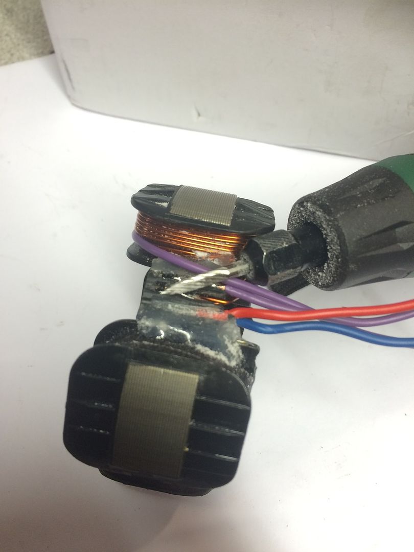
Probably better for me to add a little info to try to better show how I am going about it, this is a little more involved.
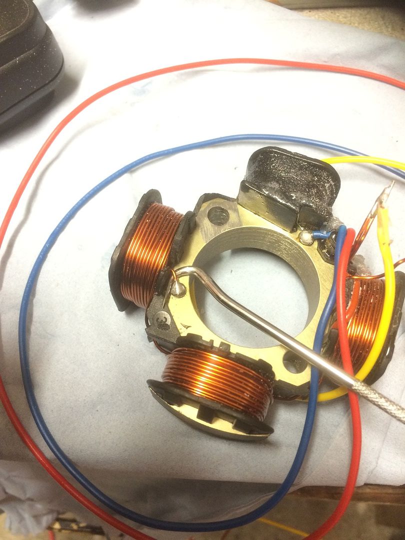
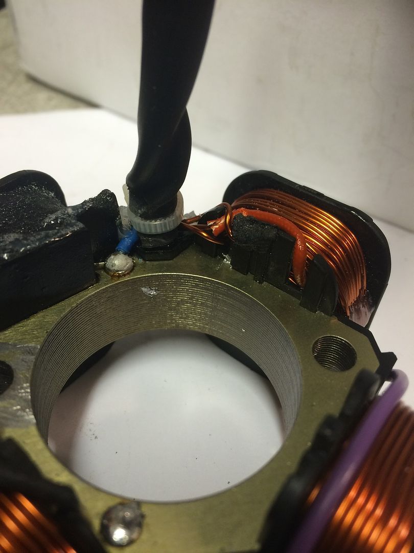
First I remove the wire tie that secures all the wires and sleeving.
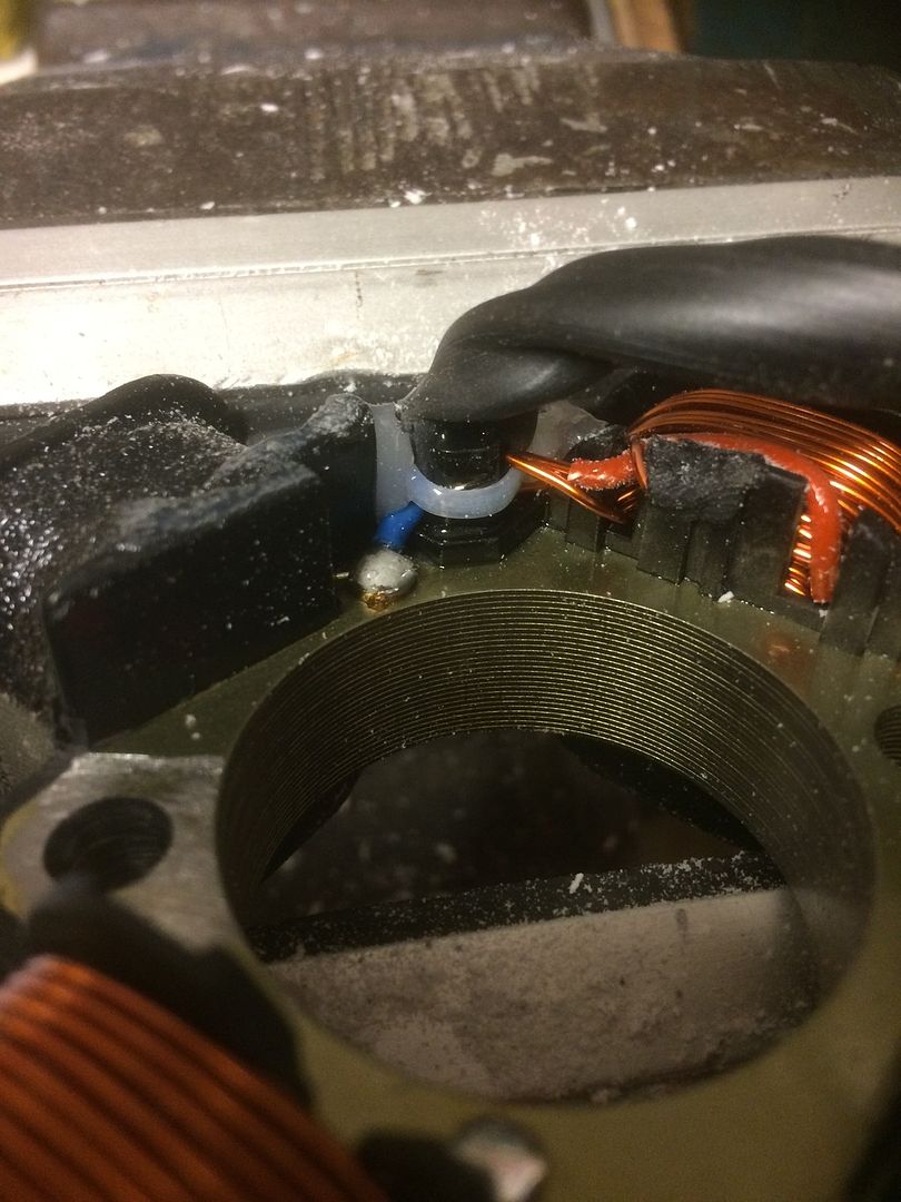
Then I removed the resin that secures and insulates all the wires and the wire tie at the post. Slowly with a fine pointed tungsten burr and a mini drill.
http://i1104.photobucket.com/albums/h32 ... vwtty0.jpg
I cut the resin back till I got down to the black plastic
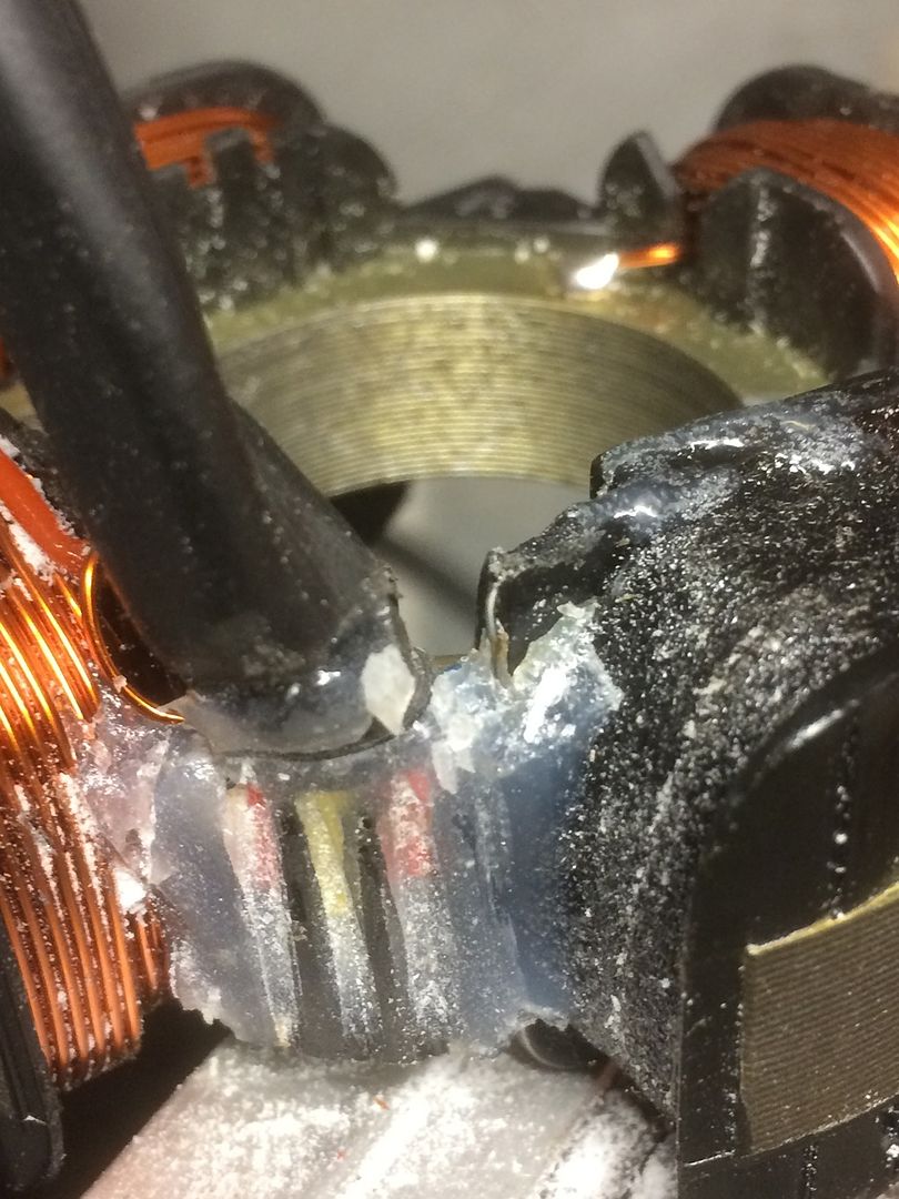
Next I carefully slid a Stanley knife blade between the plastic and the resin covered soldered wires to remove the last of the resin and free the wires.
You only need to free the two red/white and yellow/white wires.
The red and blue wires and their connections are best left alone, these are the ignition feeds and you will need to be extra careful around the LT coil as the thin wires are easily broken.
I've removed some more resin around the LT coil just to show how careful you need to be here.
If you look you can see a thin wire following the bobbin edge down to earth and if you look just a few mm to the right of the blue wire theres another slightly thicker wire which goes into the resin and connects to the red wire.
These two connections if your clumsy could easily be broken or cut through. More easily as some will use a large soldering iron to remove old resin from stators or a large cutter so extra care needs to be taken, or maybe best just stay away from that edge of the LT coil.
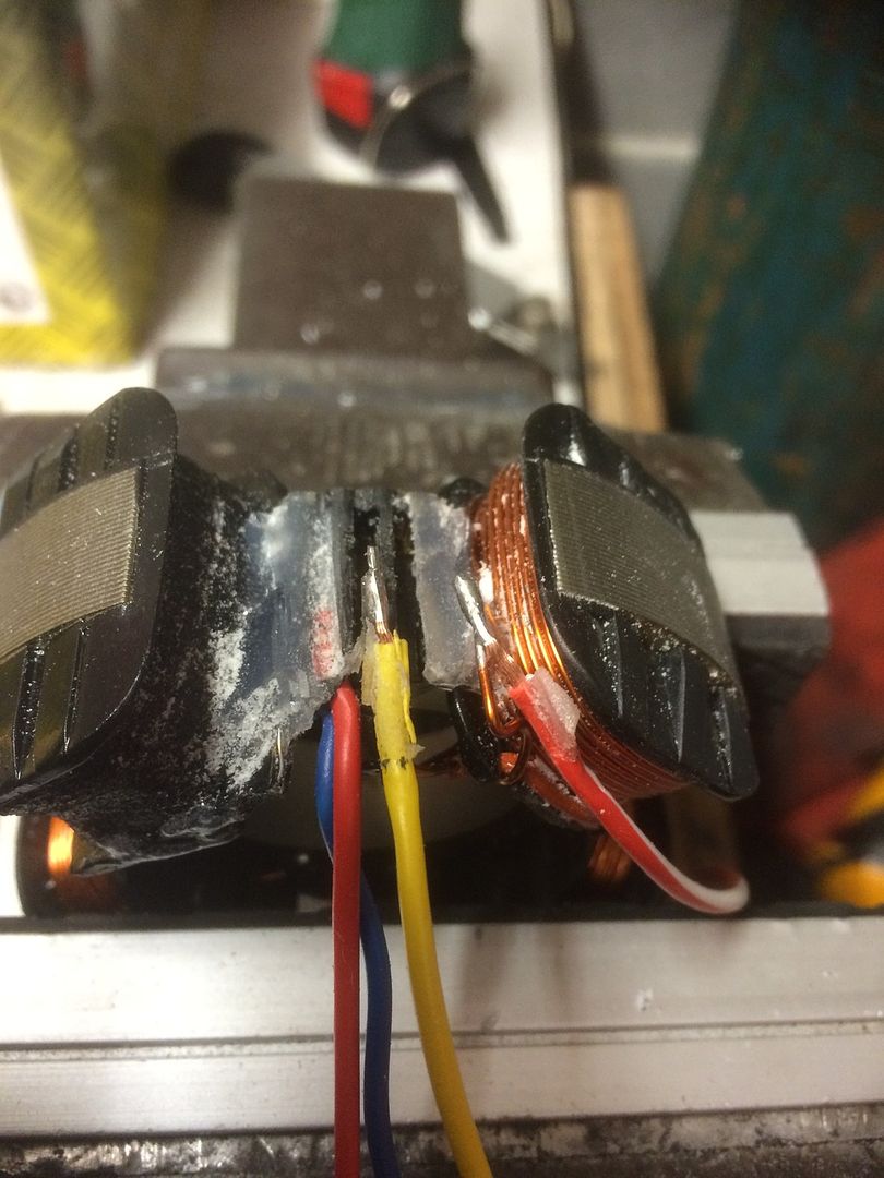
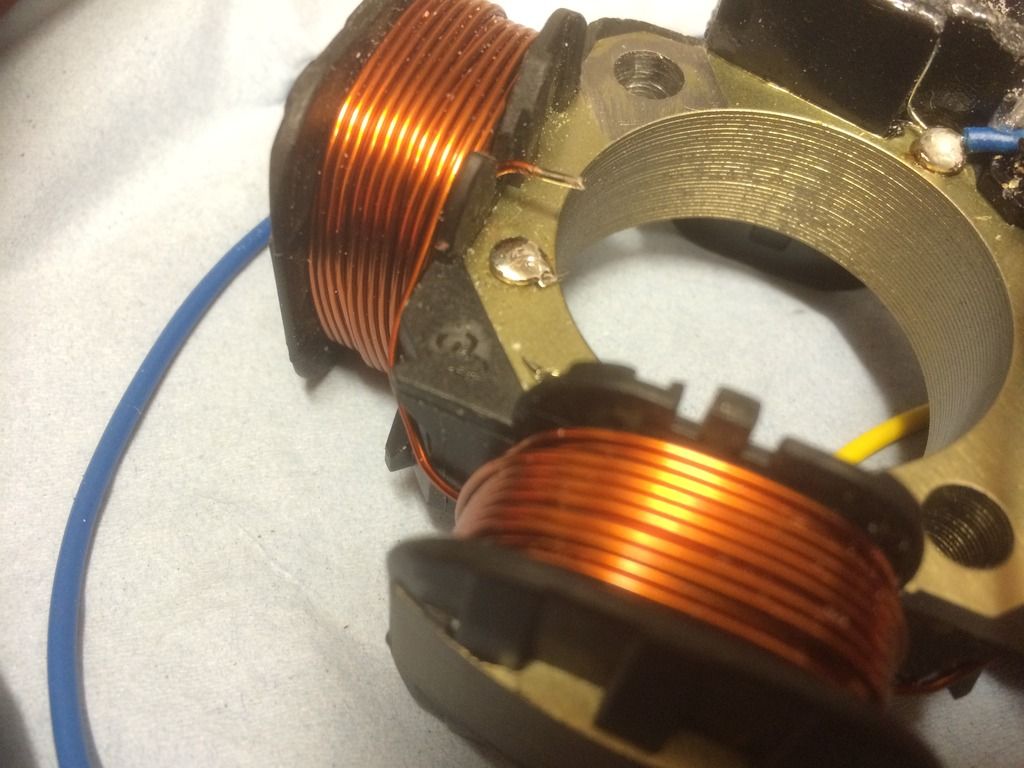
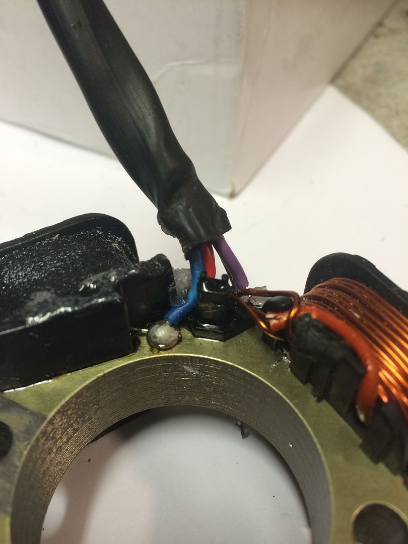
The earth wire to the back plate needs to be unsoldered.
I use the pick in place as above and a touch with a 35-50 watt soldering iron is enough to remove the wire.
Remove the single soldered red/white wire from the single lighting coil wire.
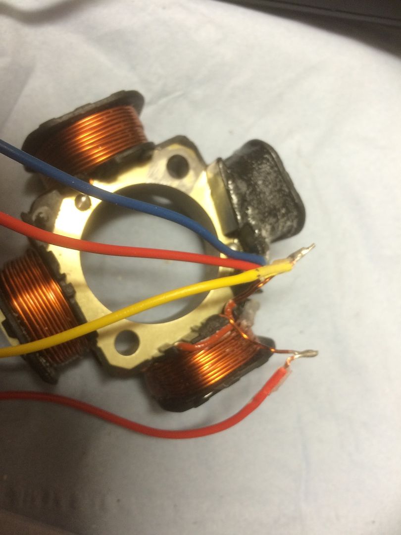
And put a pice of tape on that wire to indicate that is the single wire, I used red tape.
Then remove the yellow/white wire as its not needed.
So you now have this.
Ignition wires intact and three free ends of the lighting coils, one with a taped end.
This post is being uploaded as the work is being done so this is a work in progress.
Please wait till it's finished before replying thanks.
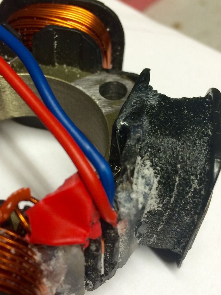
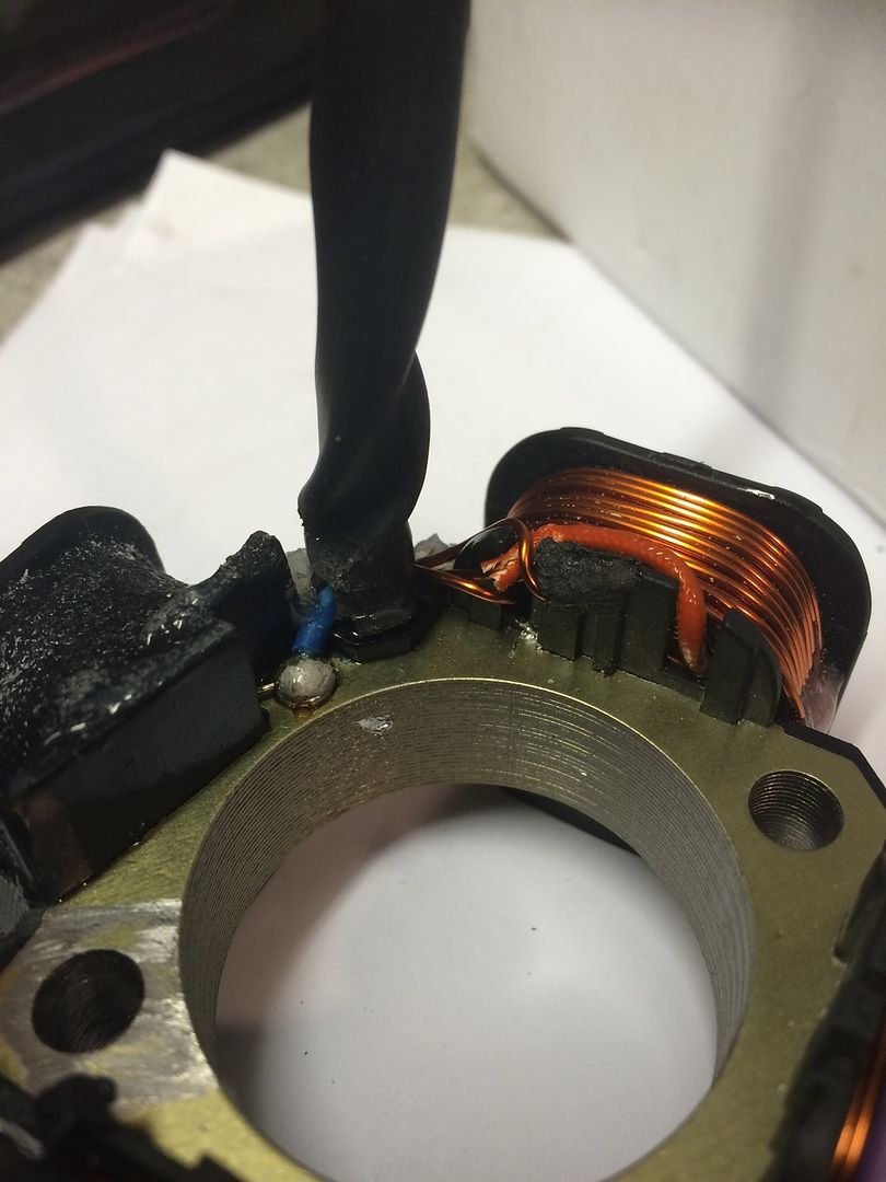
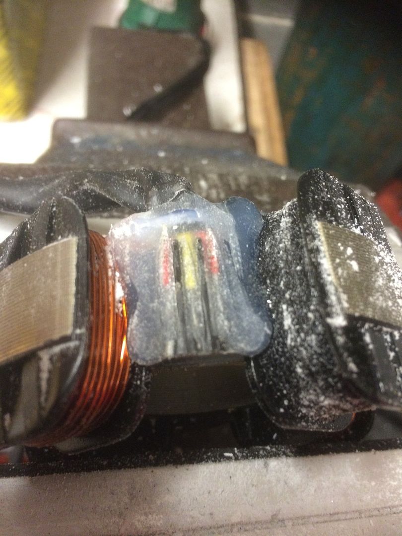
Solder the two free coil ends from the yellow/white wire, this double connection will be secured back under the resin without the yellow/white wire or any other feed wire.
Next solder a feed wire to the one free coil wire this is the one that was taped up.
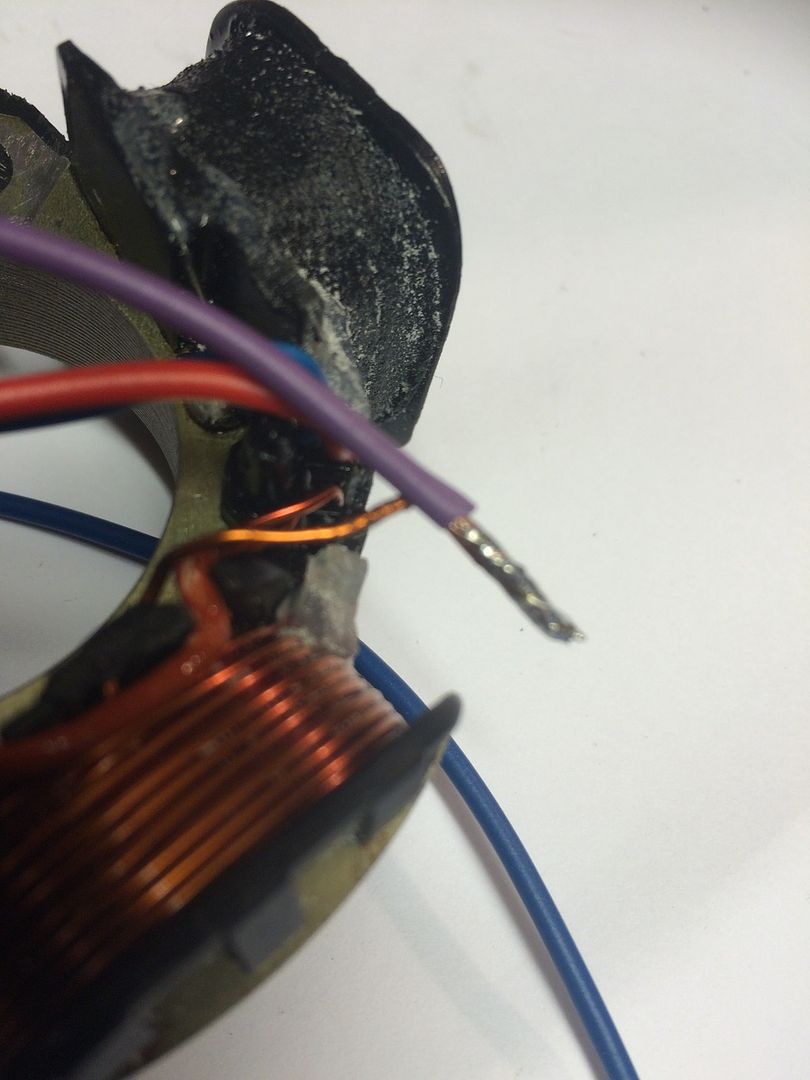
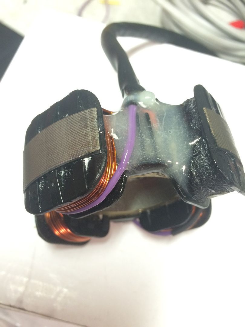
One wire soldered back on I've used thin walled Purple 32/0.2mm wire, as I just need a wire that's recognisable from the other stator wires.
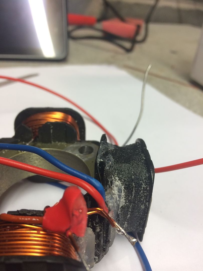
Next solder a wire (another purple) to the original lighting coils earth wire.
I think it's best to be heat shrunk at the connection.as in the next picture also showing how best to route the added wire to get it into the best position to exit the stator and avoid being trapped or caught.
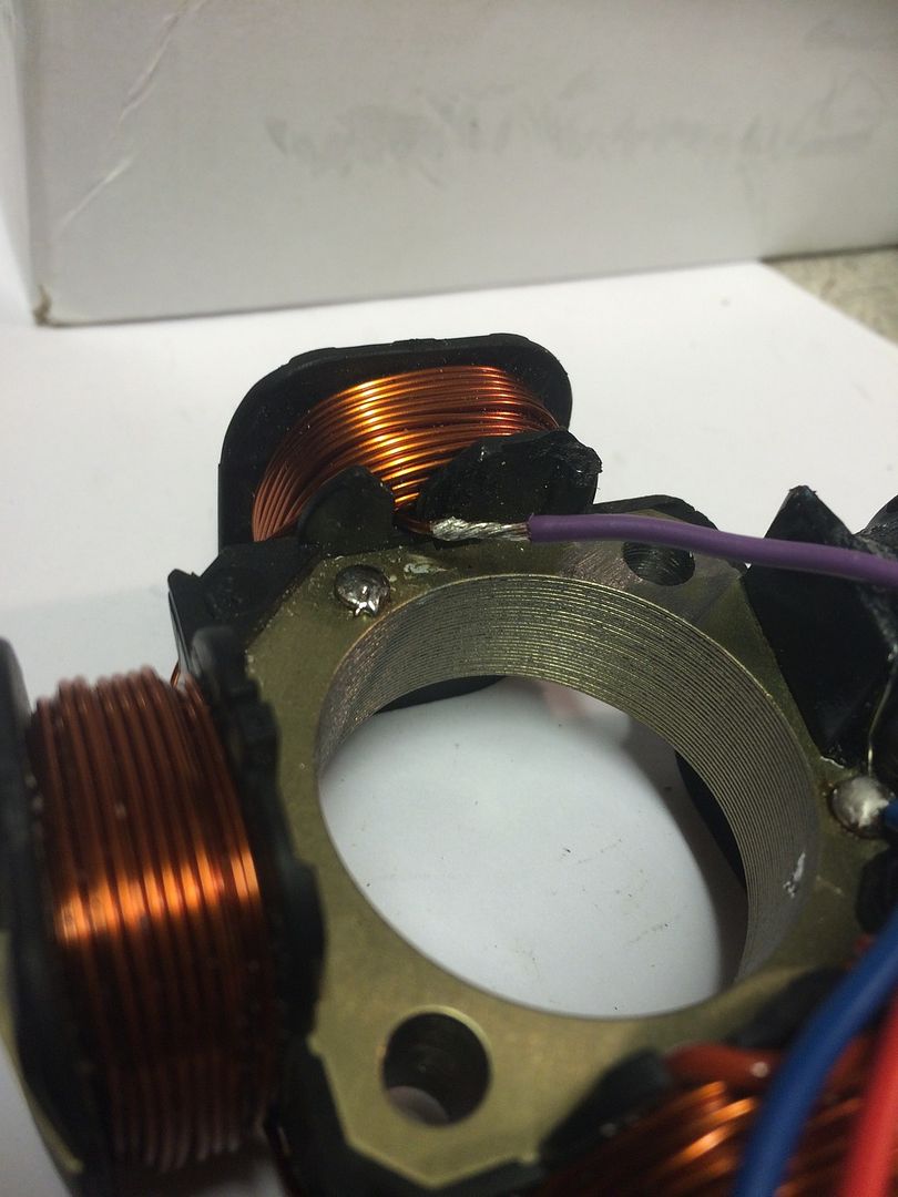
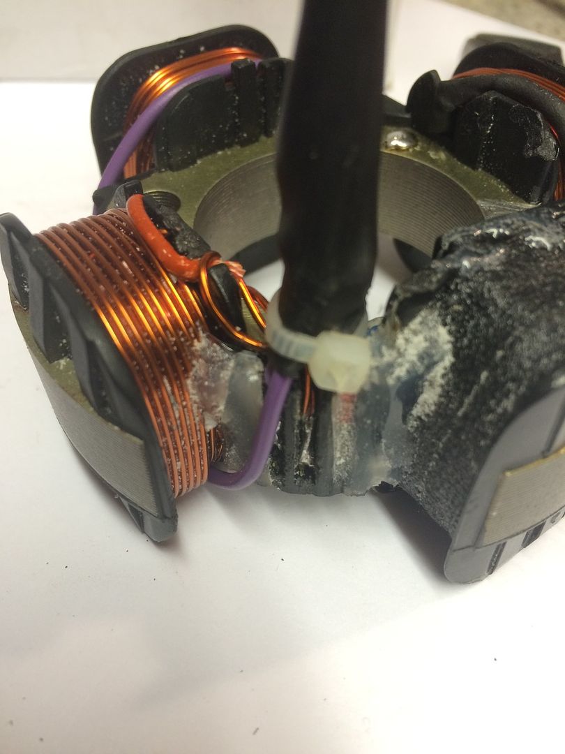
Viewed from one side showing the heat shrink soldered connection.
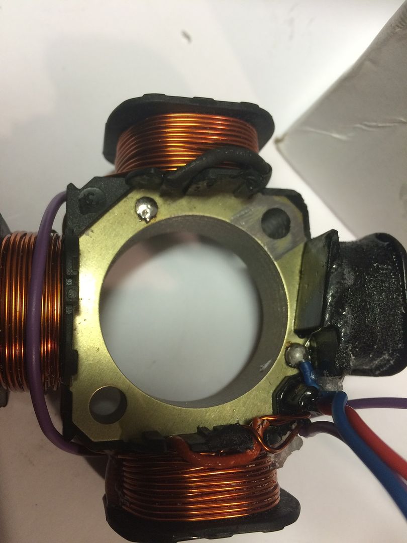
And from the other side showing the routing of the added wire to the stator loom.
I need to sleeve the wires, add a wire tie connectors and some resin next.
To remove the resin I used a small tungsten it's only 3mm wide at its widest point with a variable speed cordless mini tool. This allowed me to get a very slow removal of the resin without any accidents.
Here's a picture...
next secure the wires and sleeving to the post. The wire securing post is visible just below the sleeving.
Next pull the sleeving down make sure all the wires and soldered connections are where they should be.
Then secure the sleeving to the post with a wire tie.
Next apply resin all around the soldered wires around the end of the sleeving and the plastic post to secure and seal the connections from the elements.
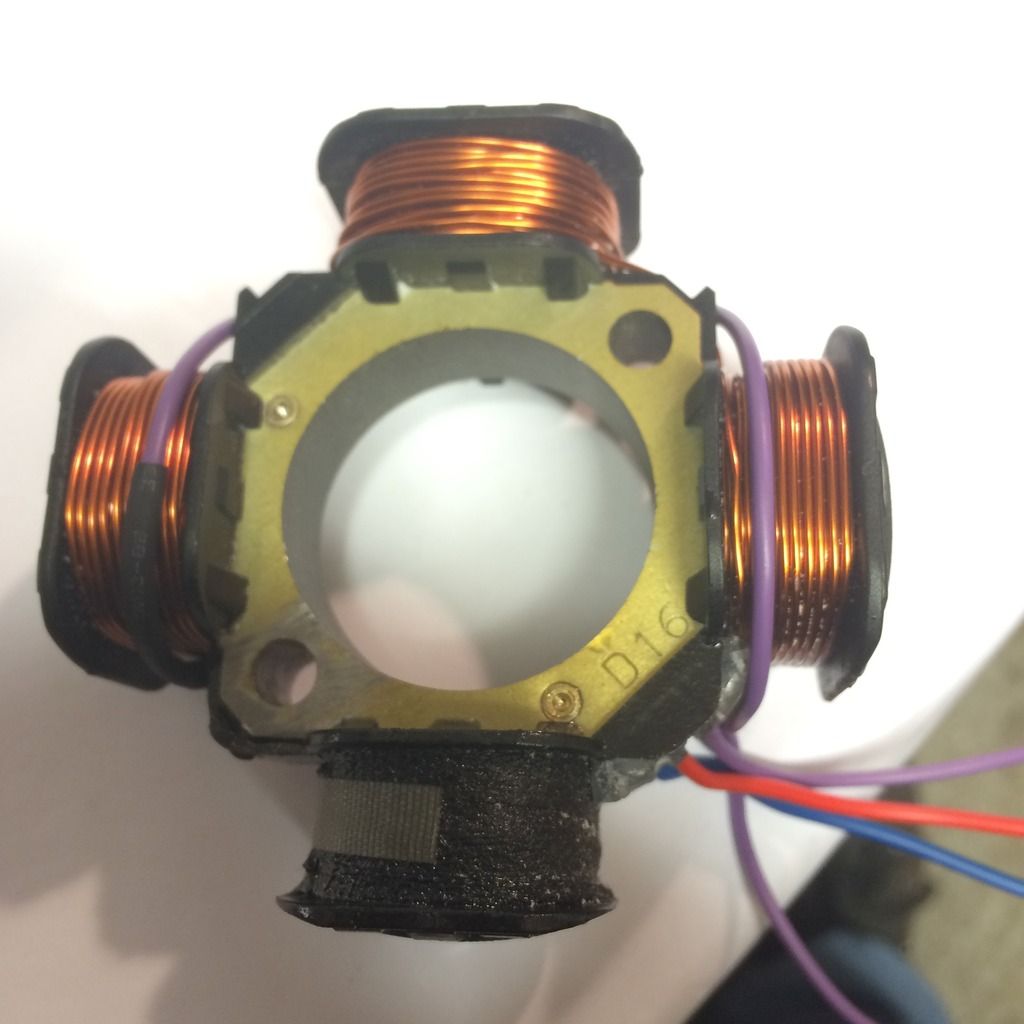
All that's left is to attach the terminals to the ends of the four wires and it's finished.
This is the basic outline.
The yellow/white wire isn't needed, it can be left unused.
The red/white wire is used as one of the feeds to the Wassell rectifier.
The other is feed is taken from the earth wire to the stator, this earth needs to be undone and a new wire connected and securely fed out from the stator to the rectifier.
This will give you the two ac feeds needed to connect to the Wassell rectifier.
That's the basic outline of how to go about it.
Probably better for me to add a little info to try to better show how I am going about it, this is a little more involved.
First I remove the wire tie that secures all the wires and sleeving.
Then I removed the resin that secures and insulates all the wires and the wire tie at the post. Slowly with a fine pointed tungsten burr and a mini drill.
http://i1104.photobucket.com/albums/h32 ... vwtty0.jpg
I cut the resin back till I got down to the black plastic
Next I carefully slid a Stanley knife blade between the plastic and the resin covered soldered wires to remove the last of the resin and free the wires.
You only need to free the two red/white and yellow/white wires.
The red and blue wires and their connections are best left alone, these are the ignition feeds and you will need to be extra careful around the LT coil as the thin wires are easily broken.
I've removed some more resin around the LT coil just to show how careful you need to be here.
If you look you can see a thin wire following the bobbin edge down to earth and if you look just a few mm to the right of the blue wire theres another slightly thicker wire which goes into the resin and connects to the red wire.
These two connections if your clumsy could easily be broken or cut through. More easily as some will use a large soldering iron to remove old resin from stators or a large cutter so extra care needs to be taken, or maybe best just stay away from that edge of the LT coil.
The earth wire to the back plate needs to be unsoldered.
I use the pick in place as above and a touch with a 35-50 watt soldering iron is enough to remove the wire.
Remove the single soldered red/white wire from the single lighting coil wire.
And put a pice of tape on that wire to indicate that is the single wire, I used red tape.
Then remove the yellow/white wire as its not needed.
So you now have this.
Ignition wires intact and three free ends of the lighting coils, one with a taped end.
This post is being uploaded as the work is being done so this is a work in progress.
Please wait till it's finished before replying thanks.
Solder the two free coil ends from the yellow/white wire, this double connection will be secured back under the resin without the yellow/white wire or any other feed wire.
Next solder a feed wire to the one free coil wire this is the one that was taped up.
One wire soldered back on I've used thin walled Purple 32/0.2mm wire, as I just need a wire that's recognisable from the other stator wires.
Next solder a wire (another purple) to the original lighting coils earth wire.
I think it's best to be heat shrunk at the connection.as in the next picture also showing how best to route the added wire to get it into the best position to exit the stator and avoid being trapped or caught.
Viewed from one side showing the heat shrink soldered connection.
And from the other side showing the routing of the added wire to the stator loom.
I need to sleeve the wires, add a wire tie connectors and some resin next.
To remove the resin I used a small tungsten it's only 3mm wide at its widest point with a variable speed cordless mini tool. This allowed me to get a very slow removal of the resin without any accidents.
Here's a picture...
next secure the wires and sleeving to the post. The wire securing post is visible just below the sleeving.
Next pull the sleeving down make sure all the wires and soldered connections are where they should be.
Then secure the sleeving to the post with a wire tie.
Next apply resin all around the soldered wires around the end of the sleeving and the plastic post to secure and seal the connections from the elements.
All that's left is to attach the terminals to the ends of the four wires and it's finished.


