LCGB Forums

The ability to post messages is restricted to LCGB members. Any questions contact us at lcgbadmin@googlemail.com

Head cowling improvements

Need help with a tuning kit, how do you tune your scooter, which kit should I choose, and all general tuning and modifcations questions are for in here.

Head cowling improvements

Postby Knowledge » Fri Jan 06, 2017 2:02 pm

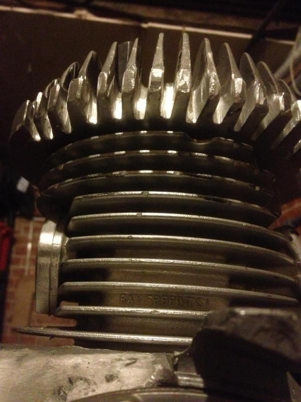
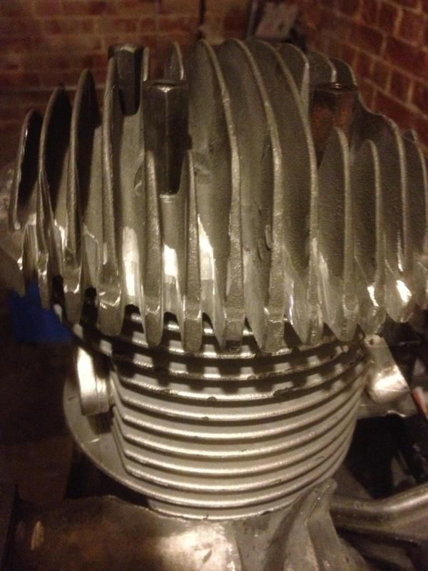
I have got a new kit with a new billet head. It is a longer stroke and needs plenty of cooling.

I have acquired and lightened a long-fin flywheel, and I am using the deep flywheel-cowling, which has been fettled to eliminate cavitation.

I have been working on the head cowling too, partly to make allowance for the wider flywheel cowling, but also to make a bit more space beneath the cowling for the air to flow. I am happy with my reasoning for this, but I thought I would start a thread on the forum so people could join in with my "fettle, learn, share" approach to re-engineering the Lambretta.
Image

Image

Let's have a discussion about what the air should be doing inside the cowling, how long it should be there, and how it should be allowed to escape.
User avatar
Knowledge
 
Posts: 1957
Joined: Sat May 31, 2014 11:42 am
Location: Ipswich

Re: Head cowling improvements

Postby dickie » Fri Jan 06, 2017 4:04 pm

For maximum overall heat transfer you need the cool fresh air to come in at the coolest point (cylinder Base) then rise toward the hottest point (head or maybe exhaust stub) then exit.

However, if you have a critical point (like the head) then it can pay dividends to put the coolest air straight onto that point.

I use a lot of heat exchangers at work but they're easier to judge because you simply need max heat transfer. There is no critical point.
dickie
 
Posts: 1759
Joined: Thu Oct 02, 2014 12:32 pm
Location: Tyne and Wear

Re: Head cowling improvements

Postby Warkton Tornado No.1 » Fri Jan 06, 2017 4:41 pm

Very interesting Knowledge!

To add my two pennies worth, I think Dave Webster was correct in wishing to maintain the internal deflector & I’ve always strived to either keep them in place by adding supports to them or bolt/rivet in a sturdier 16 swg replacement.

I made a fibreglass cowling that scooped in air from below as current Group Four but was topped off with an electric fan for cooling when there was no airflow via forward progress.

However, there was little known benefit as Group Four use AvGas which is so capable of ensuring the engine runs cooler, so the idea was abandoned.

The principle could be applied to any full bodied Lambretta but the space occupied by the toolbox is taken by the fan & mouldings.

I’m just saying, though, all of that as I think your logic is very sound & I think what you’re doing here makes a lot of sense. ;)
Warkton Tornado No.1
 
Posts: 2121
Joined: Sun Jan 11, 2015 1:27 pm

Re: Head cowling improvements

Postby coaster » Fri Jan 06, 2017 5:24 pm

What's the chimbley on the top for Martin?

Correction, I can see from the other photo that it's for the plug but surely that is going to make changing the plug near impossible :?
User avatar
coaster
 
Posts: 2647
Joined: Fri May 30, 2014 1:00 pm
Location: Norfolk, Flying 8 Balls

Re: Head cowling improvements

Postby Meds » Fri Jan 06, 2017 6:52 pm

Great ideas, there are a couple of things than you may need to consider when increasing the volume of the cowl.
If there is too much room round the outside of the cowl then the air will flow around the cylinder and head and not across the fins. Using baffles will direct the air across the fins where the heat is picked up.
The cylinder fins need to be a bit rough as this helps break up the flow increasing turbulence which aids heat transfer.
taffspeed use to set the space between the flywheel cooling fins and the cowl very small to make the air flow into the cowl more efficient and ( I suspect increase the air velocity hence promoting turbulent flow)
Meds
 
Posts: 431
Joined: Sat May 31, 2014 10:08 pm

Re: Head cowling improvements

Postby Knowledge » Fri Jan 06, 2017 7:10 pm

coaster wrote:What's the chimbley on the top for Martin?

Correction, I can see from the other photo that it's for the plug but surely that is going to make changing the plug near impossible :?


The chimneys, which have both been cut down a little now, are for the plug and the bolt that secures the cowling. The plug socket was over the plug when I welded the "chimney" on, so it will come out. I had to move the hole for the plug, and this was the easiest way to re-make the hole in its new location/ It also stops cables rubbing up against the plug/plug cap, though this scooter configuration* will allow me to use the standard cable diverter near the choke (though I have no choke lever in this location)

Martin

* My current scooter has a lift-off fibre-glass rear end, and access to the plug is not a problem
User avatar
Knowledge
 
Posts: 1957
Joined: Sat May 31, 2014 11:42 am
Location: Ipswich

Re: Head cowling improvements

Postby Knowledge » Fri Jan 06, 2017 7:13 pm

Thanks Meds.

There is only a couple of millimetres extra around the head, but this billet head does not have very deep fins so it is quire hard to push air through them, as you would with the original head. However, the fins do have a rather neat rough-cut finish. I hadn't really noticed that until you pointed it out.
User avatar
Knowledge
 
Posts: 1957
Joined: Sat May 31, 2014 11:42 am
Location: Ipswich

Re: Head cowling improvements

Postby dickie » Fri Jan 06, 2017 9:13 pm

Meds wrote:If there is too much room round the outside of the cowl then the air will flow around the cylinder and head and not across the fins. Using baffles will direct the air across the fins where the heat is picked up.


I hope I'm not hijacking your thread but I've been concerned about this on my current build. It's a TS1 225 with an avanti head and cowl. I'm concerned that the path of least resistance is around the barrel, thereby bypassing the head. I bought the head to improve cooling but I'm wondering if it's actually going to be worse.

I could fit rubber inside cowl to fill the gap but that would insulate.
dickie
 
Posts: 1759
Joined: Thu Oct 02, 2014 12:32 pm
Location: Tyne and Wear

Re: Head cowling improvements

Postby Warkton Tornado No.1 » Fri Jan 06, 2017 9:57 pm

On the subject of monitoring the heat within & adding baffles, initially, you might be able to use something like these, stuck wherever, on the barrel & head:

Thermax.JPG
You do not have the required permissions to view the files attached to this post.
Warkton Tornado No.1
 
Posts: 2121
Joined: Sun Jan 11, 2015 1:27 pm

Re: Head cowling improvements

Postby Meds » Fri Jan 06, 2017 11:56 pm

I really don't know about the air flow round an avanti head.
Ideally you would want to maximise the mass flow rate across the fins by reducing the amount of flow than can get between the cowl and the cylinder/head, forcing as much across the fins as possible. Just to complicate the issue, getting the correct cylinder to head flow ratio won't be a simple matter either as there are multiple factors including fin surface area fin heat transfer rates and how much heat you actually want to shift.I would speak to the avanti designer to find out if he had a set up in mind or a specific cowl.
A 2mm gap round the outside of the cowl doesn't sound much but as a flow area is big, but in all thins it's a compromise between what's practical and what theoretical
Meds
 
Posts: 431
Joined: Sat May 31, 2014 10:08 pm

Re: Head cowling improvements

Postby coaster » Sat Jan 07, 2017 12:23 am

Going a bit off post but with an Avanti head fitted to a non-Avanti barrel it is s good idea to remove the material from between the fins on the fan side to promote flow across the head.
Image

Image

I think Ron now does them with the metal between the fins already reduced in thickness to make this easier. You only need to to one side as the other side is in the outlet windom of the cowling.
User avatar
coaster
 
Posts: 2647
Joined: Fri May 30, 2014 1:00 pm
Location: Norfolk, Flying 8 Balls

Re: Head cowling improvements

Postby Knowledge » Sun Jan 15, 2017 12:35 am

Time the resurrect the head thread.

I have had a good look at the cowling, and realised that on the RHS of the barrel on MY barrel, the fins between the inlet manifold and the are complete isolated from the fan. If that is the case, why are these fins covered by the fan cowl if the fan cannot possibly blow any air over them?

Therefore, I have cut-back the cowling so that the fins are exposed to the air, rather than covered by a steel cover.

Image Image
On the photo on the left, you can see I have put a black dotted on the lowest fin that the air from the fan can reach.

This can only help these fins to cool. Even though this area is not a notorious hot-spot, anything that helps the barrel to cool has got to be worthwhile.

(These photos look fine on my laptop, but are rotated and distorted on my tablet. Sorry if you are getting the same distorted view, but I can't do much about it)

Please discuss the value of this mod.
Last edited by Knowledge on Mon Jan 16, 2017 2:08 pm, edited 2 times in total.
User avatar
Knowledge
 
Posts: 1957
Joined: Sat May 31, 2014 11:42 am
Location: Ipswich

Re: Head cowling improvements

Postby Scooterlam » Sun Jan 15, 2017 1:34 am

I'm surprised no one has looked at using a "chimney" affair on the exit side of the cowl dropped down into the air flow and using the resulting venturi effect to pull more cool air thru

Also wouldn't more gap between the head and cowl slow the airflow and make cooling less efficient.
Scooterlam
 
Posts: 1377
Joined: Mon Jun 09, 2014 10:59 pm

Re: Head cowling improvements

Postby Knowledge » Sun Jan 15, 2017 9:03 am

I have thought of that chimney idea but figured that cowling had too much leakage for the Venturi effect to be, errr, effective. I might be wrong, but might struggle to prove it one way or the other.

I have increased the gap between the head and the cowling by only a couple of millimetres. This CDC machines head has a lot of metal but not much gap between the fins, so any air flow through the fins will be slowed by the small gaps between fins. I figure that a flow around the head will promote flow rather than reduce it.

Once again, I will have difficulty proving this, but sometimes you have to trust your instinct.
User avatar
Knowledge
 
Posts: 1957
Joined: Sat May 31, 2014 11:42 am
Location: Ipswich

Re: Head cowling improvements

Postby Phil D » Sun Jan 15, 2017 10:21 am

I wonder if a small 12v fan couldn't be incorporated somewhere
I realise it's a harsh environment with heat vibration etc.
I used one on an old mig welder I bought that's what gave me the idea.

The type used in computers may be suitable because of their size.
Just thinking out loud so there's probably a good reason it wouldn't work.
User avatar
Phil D
 
Posts: 972
Joined: Thu Feb 12, 2015 7:37 pm

Re: Head cowling improvements

Postby Fast n Furious » Mon Jan 16, 2017 2:40 am

This is a good thread because it highlights the problems associated with using an Avanti head with traditional, TS1, RB and other standard diameter finned cylinders.
Firstly, because the diameter of the head is so large it means it needs a custom design of cowling.
Whilst this allows close containment of cooling air around the head, the opposite is now true around the cylinder.
True.... The head gets hottest and needs most cooling air flow. The problem now, is that there is so much free volume around the cylinder the flow of air will follow the path of least resistance. So, most of it will flow around that free space without it contacting the hot finned area around the cylinder and head so you end up with cold air in and cold air pissing out all over the place.
Secondly, Avanti heads can be a real pain to marry up with that 'off the shelf' choice of expansion chamber that you want to use. Impossible or at least impractical in some cases.

Frankly.... A standard size head, made from good quality aluminium alloy, either cast or machined from a billet, should work perfectly well enough providing it has sufficient density. It should weigh at least 900 grams for a big block engine. Some are less than 700g and these should only be used as paper weights.

Some years ago I did a thermal analysis using thermal imaging cameras to measure how heat migrates from a Lammy engine.
Basically, without any forced cooling applied, the head gets the hottest as you'd expect, then the lower part of the cylinder down to the exhaust port is next and finally the opposite wall above down to the inlet port. This met expectation.
With a standard cowling fitted, the analysis showed the same trend more or less. The one area which was different however, was the far side of the exhaust port (Chain side) where there was a hot spot. This was because this area can't take advantage of any forced air flow cos the exhaust stub is in the way and so relies on conduction alone to radiate heat away.
Hot spots cause distortion and we all know what distortion leads to!

I then did an airflow analysis and found that:-
A) A lot of the air produced by the flywheel was finding its way out passed the gap that exists at the base of the cowling especially the gap between the cylinder and the Mag flange.
B) The flow of air across the head fins had no designed way out. It simply tries to muddle its way out via the far side outlet aperture.
C) The outlet aperture of the cowling was too large, preventing the far side of the cylinder from getting a sufficient flow of air around this farside fin area.
D) The force of air produced by the flywheel could be improved by blanking off the gap that exists between the edge of the flywheel fins and the tab of metal on the mag flange where the upper fixing is for the cylinder cowl. (Sorry, but without photos this is hard to describe). Basically, by closing off this gap, it stops the forced air produced, from recirculating around the flywheel, therefore improving the fans efficiency. (AKA Cavitation)

Clearly, the head cowling needed improvement.
So, I modified it so that:-
A) The exit aperture was closed off, so the circulating flow now exits past the right transfer port and out through a smaller gap by the right side of the reed valve port.
B) The length of the cowl was extended down to the the lowest fin of the cylinder. This was a challenge as it meant creating a removable"'wrap around" of the exhaust stub leaving just sufficient gap for the hot air on the left side of the exhaust port to escape. Now, I get a flow of air below the exhaust port, up and around the far side, and it exits at the rear of the read valve port.
C) A removable blanking plate was attached at the base of the cowl to prevent the forced flow from escaping at the base of the cylinder.
D) A scoop was added so that the free flow of air under the moving scoot could be scooped up to cool the right side of the exhaust port that never gets any forced cooling. This only just clears my expansion chamber.
E) Another scoop was designed and fitted to the flywheel cowl to take advantage of some additional forced entry into the flywheel when at speed. (It looks like a snail shell (Conch). Lol) This works very well.
F) There are some rubberised bead strips on the internals of the cylinder cowl . This means that all flowing air has to pass between the fins of the engine (there is no freeloading) Every bit of cooling air available gets used to do COOLING. The faster I go the more cooling air I get.
G) Holes were drilled in the upper part of the cowling on the right side so hot flowing air across the head fins can exhaust properly.
H) A thin rubber bead seals the slight gap that exists between the flywheel cowling and the mag flange. ( Pedantic? I know, but it also acts as an anti-vibration solution preventing the cowl screws from coming loose! Win win.)

Gentlemen (and ladies of course) The devil is in the detail.
So how well does all this effort work?
Well...... I have a TS1/200 and it can hold the outside lane of the M1 until the tank runs dry and I can do this as often as I like or until I need fuel and a ciggy.
There is a temp sensor installed 3mm directly above the the top of the combustion chamber and I've yet to see 300 fahrenheit. A 7 grade plug works just fine.
Lambretta's have always been described as having "Marginal cooling capabilities at best", but it doesn't have to be this way.
Any side effects to be noted?
Just one.
The Conch scoop on the flywheel cowling is a great little supercharger fueled with an amalgam of air and road grid. This grit exits perfectly out of the head vents right in line with the breathing tract of the TMX35.
Luckily, I found this out after the 1st strip down inspection at 200miles before it developed into an issue. A RAM air filter has sorted that out.
Judge for yourselves by all means. But if you make these mods you will enjoy the results as I have.

See you at the next rally............ unless you've seized up. Doh. :D
Last edited by Fast n Furious on Thu Aug 03, 2017 1:37 am, edited 1 time in total.
User avatar
Fast n Furious
 
Posts: 1512
Joined: Sat Nov 19, 2016 3:56 am
Location: York

Re: Head cowling improvements

Postby ladsdad » Mon Jan 16, 2017 1:56 pm

Hi (Mr) fast & furious
Do you have or could you take some pictures of your cowl modifications?
ladsdad
 
Posts: 156
Joined: Wed May 14, 2014 9:18 am

Re: Head cowling improvements

Postby Meds » Mon Jan 16, 2017 5:01 pm

Sound like a well thought out work soulution, it would be nice to see the photos fast n furious.
Meds
 
Posts: 431
Joined: Sat May 31, 2014 10:08 pm

Re: Head cowling improvements

Postby Fast n Furious » Mon Jan 16, 2017 7:37 pm

Photographs mmmmm.
My camera makes pictures that are 5+Mb jpeg which are too big for posting I think. I need to find a way of condensing these into something more manageable. When I've figured that out I post some pics.
User avatar
Fast n Furious
 
Posts: 1512
Joined: Sat Nov 19, 2016 3:56 am
Location: York

Re: Head cowling improvements

Postby Knowledge » Mon Jan 16, 2017 8:56 pm

Sometime, you can email them to yourself and they will be automatically resized.

Otherwise, even some Microsoft picture programmes offer resizing options in the edit suite. I have to resize my photos before posting on here. A bit of a faff, but....
User avatar
Knowledge
 
Posts: 1957
Joined: Sat May 31, 2014 11:42 am
Location: Ipswich

Next

Return to Tuning & Kits

Who is online

Users browsing this forum: No registered users and 34 guests