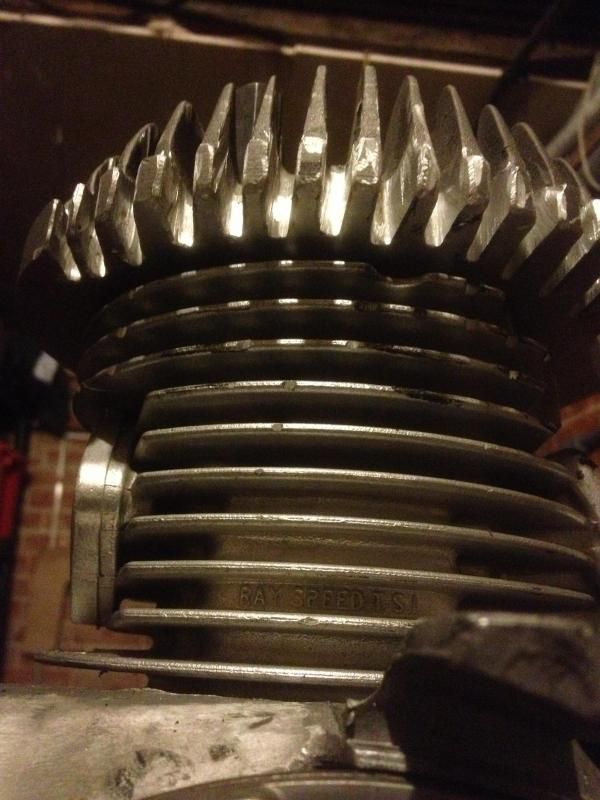
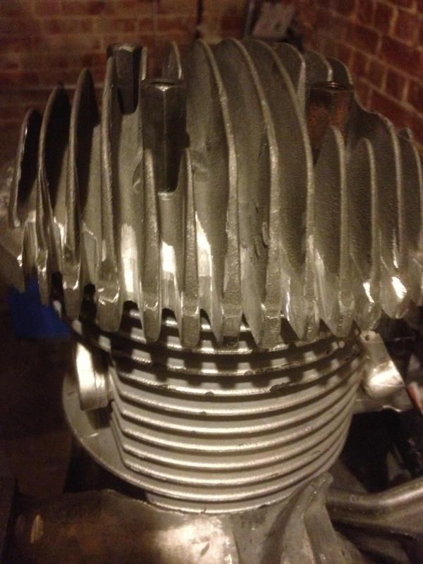
This is a good thread because it highlights the problems associated with using an Avanti head with traditional, TS1, RB and other standard diameter finned cylinders.
Firstly, because the diameter of the head is so large it means it needs a custom design of cowling.
Whilst this allows close containment of cooling air around the head, the opposite is now true around the cylinder.
True.... The head gets hottest and needs most cooling air flow. The problem now, is that there is so much free volume around the cylinder the flow of air will follow the path of least resistance. So, most of it will flow around that free space without it contacting the hot finned area around the cylinder and head so you end up with cold air in and cold air pissing out all over the place.
Secondly, Avanti heads can be a real pain to marry up with that 'off the shelf' choice of expansion chamber that you want to use. Impossible or at least impractical in some cases.
Frankly.... A standard size head, made from good quality aluminium alloy, either cast or machined from a billet, should work perfectly well enough providing it has sufficient density. It should weigh at least 900 grams for a big block engine. Some are less than 700g and these should only be used as paper weights.
Some years ago I did a thermal analysis using thermal imaging cameras to measure how heat migrates from a Lammy engine.
Basically, without any forced cooling applied, the head gets the hottest as you'd expect, then the lower part of the cylinder down to the exhaust port is next and finally the opposite wall above down to the inlet port. This met expectation.
With a standard cowling fitted, the analysis showed the same trend more or less. The one area which was different however, was the far side of the exhaust port (Chain side) where there was a hot spot. This was because this area can't take advantage of any forced air flow cos the exhaust stub is in the way and so relies on conduction alone to radiate heat away.
Hot spots cause distortion and we all know what distortion leads to!
I then did an airflow analysis and found that:-
A) A lot of the air produced by the flywheel was finding its way out passed the gap that exists at the base of the cowling especially the gap between the cylinder and the Mag flange.
B) The flow of air across the head fins had no designed way out. It simply tries to muddle its way out via the far side outlet aperture.
C) The outlet aperture of the cowling was too large, preventing the far side of the cylinder from getting a sufficient flow of air around this farside fin area.
D) The force of air produced by the flywheel could be improved by blanking off the gap that exists between the edge of the flywheel fins and the tab of metal on the mag flange where the upper fixing is for the cylinder cowl. (Sorry, but without photos this is hard to describe). Basically, by closing off this gap, it stops the forced air produced, from recirculating around the flywheel, therefore improving the fans efficiency. (AKA Cavitation)
Clearly, the head cowling needed improvement.
So, I modified it so that:-
A) The exit aperture was closed off, so the circulating flow now exits past the right transfer port and out through a smaller gap by the right side of the reed valve port.
B) The length of the cowl was extended down to the the lowest fin of the cylinder. This was a challenge as it meant creating a removable"'wrap around" of the exhaust stub leaving just sufficient gap for the hot air on the left side of the exhaust port to escape. Now, I get a flow of air below the exhaust port, up and around the far side, and it exits at the rear of the read valve port.
C) A removable blanking plate was attached at the base of the cowl to prevent the forced flow from escaping at the base of the cylinder.
D) A scoop was added so that the free flow of air under the moving scoot could be scooped up to cool the right side of the exhaust port that never gets any forced cooling. This only just clears my expansion chamber.
E) Another scoop was designed and fitted to the flywheel cowl to take advantage of some additional forced entry into the flywheel when at speed. (It looks like a snail shell (Conch). Lol) This works very well.
F) There are some rubberised bead strips on the internals of the cylinder cowl . This means that all flowing air has to pass between the fins of the engine (there is no freeloading) Every bit of cooling air available gets used to do COOLING. The faster I go the more cooling air I get.
G) Holes were drilled in the upper part of the cowling on the right side so hot flowing air across the head fins can exhaust properly.
H) A thin rubber bead seals the slight gap that exists between the flywheel cowling and the mag flange. ( Pedantic? I know, but it also acts as an anti-vibration solution preventing the cowl screws from coming loose! Win win.)
Gentlemen (and ladies of course) The devil is in the detail.
So how well does all this effort work?
Well...... I have a TS1/200 and it can hold the outside lane of the M1 until the tank runs dry and I can do this as often as I like or until I need fuel and a ciggy.
There is a temp sensor installed 3mm directly above the the top of the combustion chamber and I've yet to see 300 fahrenheit. A 7 grade plug works just fine.
Lambretta's have always been described as having "Marginal cooling capabilities at best", but it doesn't have to be this way.
Any side effects to be noted?
Just one.
The Conch scoop on the flywheel cowling is a great little supercharger fueled with an amalgam of air and road grid. This grit exits perfectly out of the head vents right in line with the breathing tract of the TMX35.
Luckily, I found this out after the 1st strip down inspection at 200miles before it developed into an issue. A RAM air filter has sorted that out.
Judge for yourselves by all means. But if you make these mods you will enjoy the results as I have.
See you at the next rally............ unless you've seized up. Doh.


